This post shows the introduction of Border router in Contiki OS. Border router or edge router is connected to internet when the other sensor nodes are reporting the data via the border router.
Implementation of this router is provided by all IOT operating systems.
Using this border router, how to transmit data to the internet, how neighbours are understood and how the routes are computed.
This example shows the implementation of Border router in Contiki OS
OS Used: Contiki 2.7
Simulator : Pooja
Open Cooja from the Desktop directly or Open the Terminal and give the following steps
$] cd /home/user/contiki-2.7/tools/cooja
$] ant run
If you want to simulate huge number of nodes then
$] ant run_bigmem
Click Add Motes -> Select Sky Mote
In the Firmware, Select the following path /home/user/contiki-2.7/examples/ipv6/rpl-border-router/border-router.c
Click -> Compile (or Clean and then Compile), once compilation is over, Click Create motes and select the number of motes (1 in this case)
In the Firmware Settings, Select /home/user/contiki-2.7/examples/ipv6/sky-websense/sky-websense.c
Click Clean and then Compile. After the compilation is over, Click Create and Select the required number of nodes (5 in this case)
So there are totally 6 motes (5 Websense motes and 1 border router mote). see Fig 1 Below. It shows one green coloured mote called border router and other yellow coloured motes 5 in numbers.
mote 1: aaaa::212:7401:1:101 for Border router
A bridge has to be made between the border router and the other motes, to enable the bridge,
Right Click Border Router Node -> Mote tools for Sky 1 -> Serial Socket (SERVER)
$] cd /home/user/examples/ipv6/rpl-border-router/
$] make connect-router-cooja
It will ask to input the super user password, after you input, the ipv6 addresses will be assigned to the motes.
You may ping it using a new terminal, with the command "ping6 aaaa::212:7402:2:202"
Step 6: Read the sensors
You can read the sensors using the ipv6 addresses by opening the firefox browser.
Open the browser and input the following addresses in a new tab
http://[aaaa::212:7401:1:101]
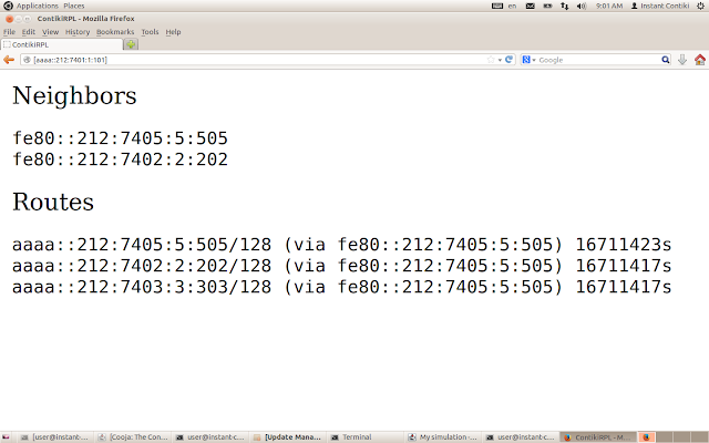
This will print the neighbours and routes from the border router
http://[aaaa::212:7402:2:202]
This example shows the connectivity of various motes with the border router.
for detailed explanation, you may look the youtube video.
T S Pradeep Kumar
Implementation of this router is provided by all IOT operating systems.
Using this border router, how to transmit data to the internet, how neighbours are understood and how the routes are computed.
This example shows the implementation of Border router in Contiki OS
OS Used: Contiki 2.7
Simulator : Pooja
Step 1: Contiki Selection
Open Instant Contiki (Which runs on VMWare or Virtual Box)Open Cooja from the Desktop directly or Open the Terminal and give the following steps
$] cd /home/user/contiki-2.7/tools/cooja
$] ant run
If you want to simulate huge number of nodes then
$] ant run_bigmem
Step 2: Selecting Border router
File - New Simulation -> Enter Simulation Name (Leave the defaults as it is ) and then Click "Create"Click Add Motes -> Select Sky Mote
In the Firmware, Select the following path /home/user/contiki-2.7/examples/ipv6/rpl-border-router/border-router.c
Click -> Compile (or Clean and then Compile), once compilation is over, Click Create motes and select the number of motes (1 in this case)
Step 3: Create WebSense Nodes (Sky Websense)
Click Add Motes -> Select Sky MoteIn the Firmware Settings, Select /home/user/contiki-2.7/examples/ipv6/sky-websense/sky-websense.c
Click Clean and then Compile. After the compilation is over, Click Create and Select the required number of nodes (5 in this case)
So there are totally 6 motes (5 Websense motes and 1 border router mote). see Fig 1 Below. It shows one green coloured mote called border router and other yellow coloured motes 5 in numbers.
 |
| Fig 1 - Cooja Simulator |
Step 4: Run the Simulation
In the Simulation Control window, you can press the Start button to start the simulation. Since this application is deployed with IpV6 for all the nodes, it can be seen from the simulation that all the motes have the ipv6 addresses like thismote 1: aaaa::212:7401:1:101 for Border router
A bridge has to be made between the border router and the other motes, to enable the bridge,
Right Click Border Router Node -> Mote tools for Sky 1 -> Serial Socket (SERVER)
Step 5: Bridge the Border Router
Open a new terminal and select the path as given below$] cd /home/user/examples/ipv6/rpl-border-router/
$] make connect-router-cooja
It will ask to input the super user password, after you input, the ipv6 addresses will be assigned to the motes.
You may ping it using a new terminal, with the command "ping6 aaaa::212:7402:2:202"
Step 6: Read the sensors
You can read the sensors using the ipv6 addresses by opening the firefox browser.
Open the browser and input the following addresses in a new tab
http://[aaaa::212:7401:1:101]
This will print the neighbours and routes from the border router
http://[aaaa::212:7402:2:202]
This will print the sensor readings like temperature and light as per the corresponding values.
See Fig 2 and Fig 3
 |
| WebSense Node |
 |
| Border Router |
for detailed explanation, you may look the youtube video.
This is the same principle that allows MIMO to increase a wireless router's speed and performance. long range wifi router
ReplyDelete